Image and descriptive information courtesy of Tom Ellis
Image and descriptive information courtesy of Tom Ellis
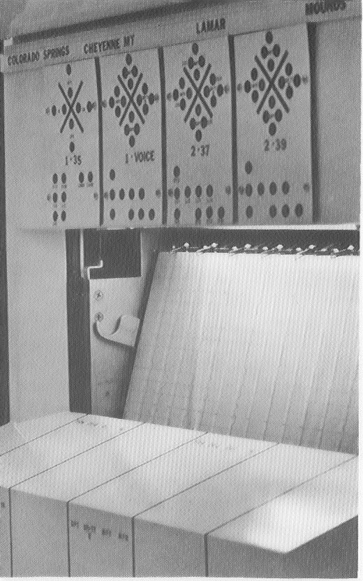
Heated pins at the top of the graphs tracked the service circuit usage (common control equipment) on temperature-sensitive graph paper. This provided a real time "track record" for each AUTOVON Switch and also provided feedback to the Watch Supervisors when Network Management Controls were being effected during abnormal network conditions.
The numbers just underneath the "X" quadrant for a switch (1-35 for Colorado Springs or 2-39 for Lamar) were to designate which Full Period (FP) Circuit was associated with the switch and the two-digit Speed Calling Number for that switch's testboard. There were 3 or 4 Full Period Voice Circuits connecting all of the CONUS AUTOVON switches to the Dranesville AUTOVON Network Management Center. One or more of the Full Period circuits could be switched or connected together so a watch supervisor could "control" more switchers on one phone if necessary.
Normally, each testboard had a speaker monitoring the FP Voice circuit and could respond to a verbal call from Dranesville. The Speed Calling was used in the event a verbal call got no immediate response.
Updated on July 25, 2004 at 21:18 by Albert LaFrance